Here is a super simple SSB/CW receiver for 80Mtr. and 40Mtr. The receiver uses a handful of normally available components.
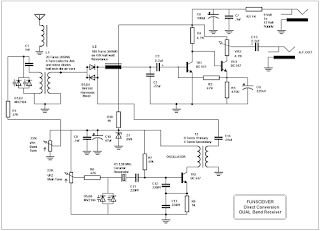
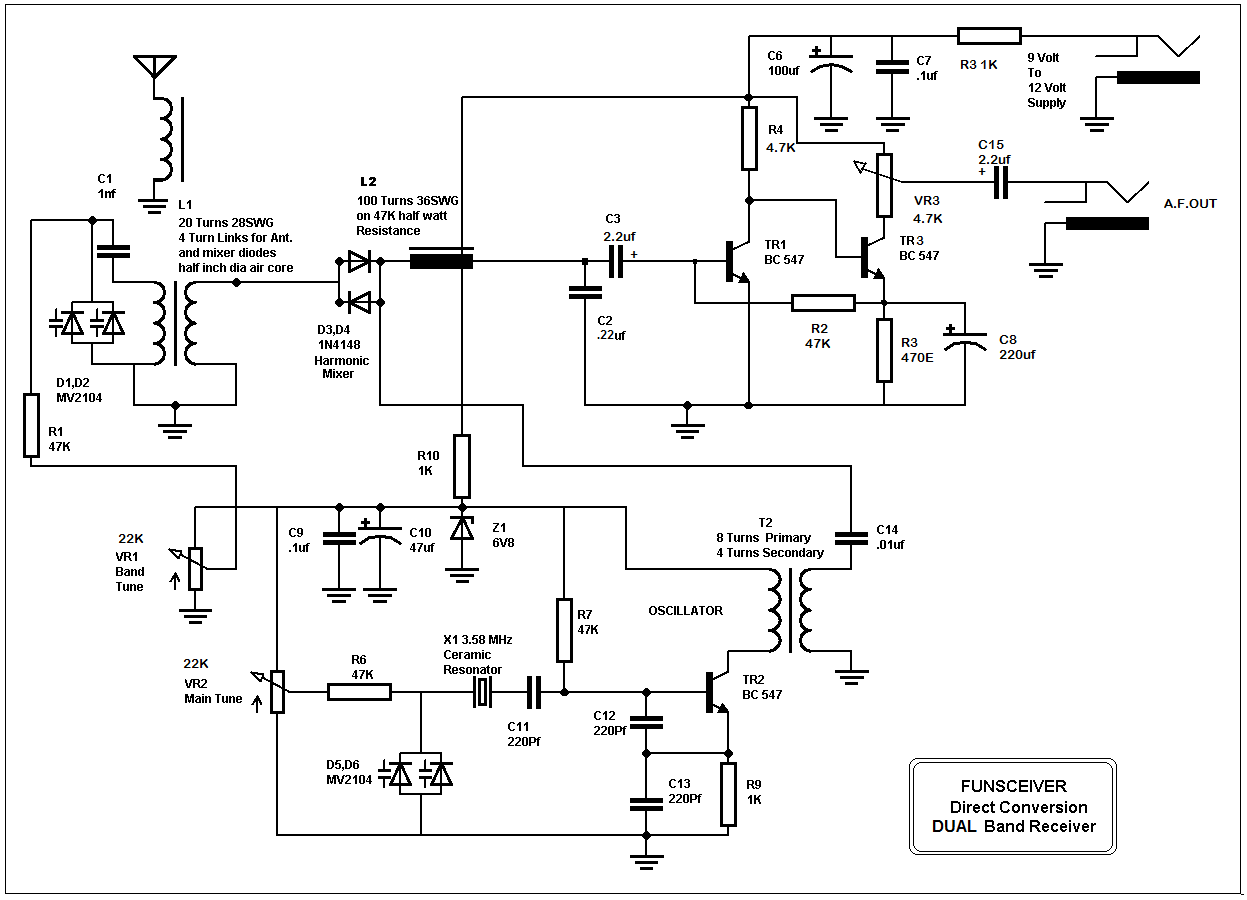
The complete circuit of the receiver is given in figure below. The input signal from the antenna is coupled through a varicap tuned tank circuit wired around L1, an air core coil. I employed varicap tuning as normal variable capacitors are difficult to find these days. I used varicaps but if you couldn't find, you can use normal diodes like 1N5804 etc.
The desired band of input signals are selected by this tuned circuit and is fed to the Polyacov’s mixer wired around high speed switching diodes D1,D2. Both of these are connected back to back and thus they function as a second harmonic mixer. For coverage of 80Mtr. band you can remove either one of mixer diodes or for reception of both bands a suitable switching arrangement can easily be devised.
TR2 is wired as a collpit’s oscillator to provide local oscillator signal for mixing. A 3.58MHz ceramic resonator is used to generate RF signal to avoid the need of any alignment of the receiver. These resonators are common in local markets or can be salvaged from any old digital desk phone, since almost every phone uses them in dialing circuit. The oscillator provides good coverage of both 80 and 40 meter band. The output signal from the oscillator is coupled through bifilar transformer T2 and C14 to the diode mixer. T2 is wound on a surplus pignose balun core. As I mentioned earlier the pair of back to back diodes acts as a harmonic mixer providing reception of 7 MHz band. For receiving 3.5 MHz band either one of the diode can be removed. For a dual band reception a switching arrangement can be implemented.
As a signal of equal frequency to the input signal is mixed in the diode mixer, the detection of the signal occurs and the output audio signals are filtered through low pass filter built around L2/C2. L2 can be wound on a 47K half watt resistor. About 100 turns of 36 SWG or similar thin wire are sufficient.This filter filters out any RF component from the audio signal and the filtered audio signal is then amplified through a two stage direct coupled AF amplifier designed around transistor TR1 and TR3. This low noise AF amplifier provides about 95 dB of gain. The output signal trough VR3 is then routed to the output phono socket. I used BC547 transistors but they can be replaced by 2N3904 or similar general purpose NPN transistors.
The output of this receiver can directly drive a pair of high impedance headphones or can be coupled to the input of any audio player or to a set of computer speakers with internal amplifier circuit. The receiver provides reception of CW and SSB signals as well as it has the ability to copy many digital modes if connected to a PC with appropriate software. In spite of its ultimate simplicity, with a resonant antenna like a dipole it provides a pleasing audition of an entire gamut of weakest radio signals, just like a window in the air.
Those desiring a standalone receiver can use the AF amplifier circuit ahead of VR3 to avoid need of its output coupling to an external source. A suitable amplifier is given in figure below.

No comments:
Post a Comment